Master-Slave Hydraulic Cylinder: How Does Sensorless Hydraulic Synchronization Work?
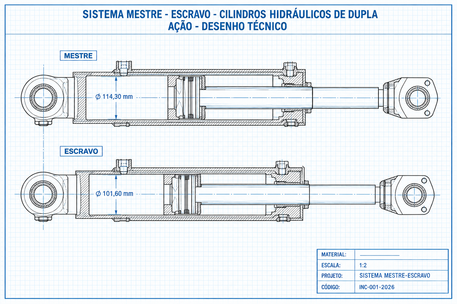
Understand how master-slave hydraulic cylinders synchronize multiple actuators without sensors, how to calculate master and slave displacement areas, and how this solution compares to flow dividers and electronic servo synchronization.
A master-slave hydraulic cylinder system consists of two or more hydraulic actuators operating in precise synchronization through a series hydraulic circuit, without relying on external position sensors or proportional servo valves. The master cylinder displaces fluid from its annular (rod) side in an exact volume engineered to match the volume required to stroke the full-bore piston of the slave cylinder, ensuring both advance and retract at identical speeds and positions.
At INCOCIL, we have engineered and manufactured master-slave hydraulic cylinder systems under the PATROL® brand for over 45 years, primarily for applications requiring precise leveling under heavy loads, such as scissor lift tables, agricultural planters, heavy equipment, and industrial presses. This article explains the physical principles behind series synchronization, how cylinder bores and rod sizes are calculated, and compares this mechanical-hydraulic solution against rotary flow dividers and closed-loop electronic synchronization.
How does master-slave hydraulic cylinder synchronization work?
Synchronization occurs because the fluid displaced by one cylinder serves directly as the hydraulic supply for the next, rather than having both actuators receive independent fluid flow from the pump. This direct interconnected fluid loop defines a series circuit.
During extension, pump pressure enters the full piston cap side of the master cylinder. As the master piston advances, it displaces oil from its annular rod end (the cross-sectional annulus between the tube bore and the piston rod diameter) through a dedicated hydraulic line directly into the full piston cap end of the slave cylinder. This displaced fluid is solely responsible for extending the slave cylinder: there is no secondary pump supply line feeding the slave in this circuit. Fluid from the slave cylinder's annular rod side returns directly to the reservoir.
During retraction, fluid flow is reversed through the same circuit: pump pressure is directed into the rod end of the slave cylinder, which forces oil from its full piston cap end back into the rod end of the master cylinder, retracting both actuators simultaneously. Because identical fluid passages are used in both directions, the same geometric area ratios that guarantee synchronized extension also ensure synchronized retraction.
The practical outcome: neither cylinder can move independently without the other moving proportionally. No position sensors, electronic controllers, or proportional flow valves are required. System precision relies entirely on two fundamental factors: precise engineering of cylinder area ratios and rigorous control of internal seal bypass leakage.
How is synchronization displacement calculated between master and slave?
The synchronization condition is straightforward in theory yet demanding in manufacturing: the oil volume displaced by the annular rod side of the master cylinder across its entire stroke must exactly equal the oil volume accepted by the full cap end of the slave cylinder.
In terms of effective area (since both cylinders share an identical stroke length):
Master Annular Area = π/4 × (D_master² − d_master_rod²) Slave Full Piston Area = π/4 × D_slave²
There is no rigid bore ratio between master and slave cylinders. At INCOCIL, cylinder bores are sized based on the specific load requirements provided by the customer for each lifting point (you can simulate areas and forces using our hydraulic cylinder calculator), and the master cylinder rod diameter is custom-engineered so that its resulting net annular area matches the full cap area of the selected slave cylinder.
Real-world engineering sizing example
The following dataset represents an actual INCOCIL manufacturing project, with internal part numbers anonymized for the purposes of this article:
| Cylinder | Role | Bore (ID) | Rod | Stroke |
|---|---|---|---|---|
| M-114 | Master | Ø 114.30 mm | Ø 52.39 mm | 280 mm |
| E-101 | Slave | Ø 101.60 mm | Ø 44.45 mm | 280 mm |
Calculating effective working areas:
- Master Annular Rod Area: π/4 × (114.30² − 52.39²) ≈ 8,104.8 mm²
- Slave Full Piston Cap Area: π/4 × (101.60²) ≈ 8,106.6 mm²
The geometric variance between both effective areas is approximately 0.02%, well within standard precision manufacturing tolerances. It is this precise area match, rather than round nominal diameters, that guarantees synchronization.
An important technical distinction must be highlighted: this 0.02% area variance is a fixed geometric characteristic of standard tube dimensions, not a functional flaw. Over a 280 mm stroke, it equates to less than 0.1 mm position differential between master and slave, repeatable on every cycle without accumulating over time. It is not what necessitates rephasing compensators; the true reason for compensator valves is addressed in the next section.
What force can a master-slave cylinder pair deliver?
This is the most common technical question regarding series synchronization, and the answer defies two intuitive misconceptions. The combined force of the assembly is neither restricted to what the slave cylinder could produce alone, nor does the slave simply exert the full independent force of the master.
What actually occurs is internal hydraulic pressure rebalancing. Because the cylinders operate in series, pump pressure acts directly only upon the full cap end of the master cylinder. The intermediate pressure connecting the master's annular side to the slave's piston side is variable: it self-adjusts dynamically to balance whatever opposing load each cylinder is supporting.
Performing a static force balance for each actuator (P = working pump pressure, A₁ = master full cap area, Aₐ = master annular area = slave cap area, P₁ = intermediate circuit pressure, tank return line unrestricted):
- Master: P × A₁ − P₁ × Aₐ = F_master
- Slave: P₁ × Aₐ = F_slave
Summing both equations cancels the intermediate pressure term, yielding a clean relationship:
The total combined force delivered by the pair (the sum of the load carried by the master and the load carried by the slave) is strictly limited by the system working pressure multiplied by the full piston cap area of the master cylinder, the first in the series. This is exactly the same force that the master cylinder would exert alone under identical operating pressure if it were working without a slave. The slave neither increases nor decreases total lifting capacity: it splits the available hydraulic power between multiple mechanical points according to actual load distribution.
Critical engineering consideration: pressure intensification
Because the intermediate circuit operates under its own pressure (P₁), which varies independently of pump supply pressure, pressure intensification can occur as documented in fluid power technical literature (Hydraulics & Pneumatics / Power & Motion Tech). In the numerical example examined here, the master cylinder cap area is roughly 1.27 times its annular rod area. Consequently, under an unbalanced load condition where the slave carries nearly the entirety of the load, intermediate line pressure can rise up to 27% higher than nominal system relief pressure. Hoses, fittings, manifold valves, and the slave cylinder itself must be rated to safely withstand this intensified pressure margin, rather than just nominal supply pressure.
Why is internal bore finish critical in this system?
Master-slave synchronization requires that internal fluid volumes remain rigorously balanced throughout the operating life of the equipment. Unlike the small geometric machining variance discussed earlier (which is fixed and non-accumulative), internal piston seal bypass leakage is progressive: any seal wear bleeds a minute volume of oil out of the closed circuit on every stroke. Because this oil is not automatically replenished during the stroke, master and slave alignment gradually drifts cycle after cycle.
To correct these accumulated drift errors, master-slave systems incorporate a rephasing compensator valve at the stroke extremes (end-of-stroke rephasing) in one or both cylinders, which re-equalizes fluid volumes upon full extension or retraction. This mechanism also automatically bleeds trapped air from the hydraulic circuit during commissioning, eliminating manual bleeding at hose ports.
What happens if sizing is incorrect or internal leakage occurs?
If master-slave area ratios are improperly calculated or if internal piston bypass leakage exceeds engineering tolerances, the two actuators will no longer extend and retract at matching velocities. Because they typically support different ends of the same rigid structure (such as opposite ends of an industrial lift table), progressive misalignment causes mechanical binding, tilting, or catastrophic structural jam under load.
In our design, manufacturing, and testing experience, internal leakage prevention is the single most critical quality parameter in master-slave cylinder production. It is an issue we frequently see when inspecting failed cylinders from other manufacturers. For this reason, high-precision cylinder honing services for internal bore finish and full-pressure holding tests — meeting the standards of our specialized cylinder maintenance — are mandatory quality control gates at INCOCIL before shipping.
Master-slave, rotary flow dividers, or electronic synchronization: which to choose?
There are three primary methods for synchronizing hydraulic cylinders, each presenting distinct trade-offs in cost, accuracy, and operational complexity.
| Criterion | Master-Slave (Series) | Flow Divider Valve | Electronic Servo Synchronization |
|---|---|---|---|
| Operating Principle | Volumetric displacement equality between interconnected cylinders | Divides pump output flow into fixed proportional streams | Linear position sensor on each cylinder + PLC-controlled proportional/servo valves |
| External Sensors | None required | None required | Required (high-accuracy linear transducers on each cylinder) |
| Typical Accuracy | Governed by internal seal leakage control; zero cumulative error with end-of-stroke rephasing | Gear-type dividers: ~1% to 3% flow split error; spool-type dividers can reach up to 15% | Highest achievable accuracy; positional error within 0.001 to 0.002 in (0.025 to 0.05 mm) in closed-loop servo systems |
| Installation Complexity | Low (two hydraulic interconnect lines between actuators) | Moderate (requires external divider valve block, relief lines) | High (wiring, sensors, PLC programming, PID closed-loop tuning) |
| Relative Cost | Lowest: no electronic hardware or proportional valves | Intermediate: cost of rotary flow divider valve plus safety relief valves | Highest: linear transducers, servo/proportional valves, and PLC controller increase acquisition and lifecycle maintenance costs |
| Maintenance | Dependent on internal seal integrity and periodic rephasing | Subject to internal divider gear/spool wear and gradual flow skew | Requires transducer calibration, wiring maintenance, and periodic control loop retuning |
Series master-slave synchronization is the simplest and most cost-effective solution when cylinders can be custom-engineered from the initial design phase to achieve matching effective areas, as in industrial scissor tables and presses with defined support geometries. Rotary flow dividers are best suited when retrofitting existing single or double-acting cylinders with identical bores. Electronic servo synchronization is justified when extreme precision is non-negotiable, when tolerating high electronics cost, or when synchronizing more than two independent axes requiring real-time dynamic trimming.
Where are master-slave hydraulic cylinders most commonly used?
In INCOCIL's custom manufacturing operations, master-slave systems are predominantly engineered for:
- Heavy-duty industrial scissor lift tables, where two or more lifting points must elevate perfectly level.
- Synchronized industrial stamping and forming presses, preventing uneven tool descent and die galling.
- Platform and vehicle lifting mechanisms.
- Agricultural planters and seeding toolbars, where planting wings must raise and lower in level unison.
- Precision material handling fixtures where electronic sensors would be vulnerable to contamination, vibration, or severe outdoor conditions.
Do you have an engineering project requiring synchronized actuators or need assistance calculating cylinder area ratios? Our team designs and manufactures custom hydraulic cylinders engineered specifically for your application. Contact our engineering specialists or explore our full line of industrial hydraulic cylinders.
Frequently asked questions
Does a master-slave hydraulic cylinder require a position sensor?
No. Synchronization is maintained mechanically by volumetric fluid displacement calculated into the cylinder area geometry. Position transducers and encoders belong to electronic feedback loops, not master-slave series circuits.
Do the master and slave cylinders have to share the same diameter?
No. The bore sizes are sized independently based on force requirements at each load point. What must match is the annular rod area of the master and the full piston cap area of the slave, not their outer barrel diameters.
Can multiple slave cylinders be driven by a single master?
Yes. While a 1:1 master-slave pair is the most common configuration engineered at INCOCIL, volumetric series chaining can be expanded to multiple slave actuators when application requirements dictate.
What causes synchronization drift over extended operating periods?
Internal seal bypass leakage due to friction wear or non-compliant barrel surface finish, rather than slight manufacturing dimensional tolerances (which are fixed and non-accumulative). Progressive internal leakage over repeated cycles is what necessitates rephasing compensator valves and makes internal bore honing a vital quality requirement.
Consulted references
- Power & Motion Tech (Hydraulics & Pneumatics) — "Book 2, Chapter 22: Synchronizing Cylinder Movement": https://www.powermotiontech.com/technologies/other-technologies/article/21884338/book-2-chapter-22-synchronizing-cylinder-movement
- Mobile Hydraulic Tips — "What Type of Flow Divider Is Best for My Application?": https://www.mobilehydraulictips.com/what-type-of-flow-divider-is-best-for-my-application/
- Sun Hydraulics — Technical Datasheet FSCSXAN (flow divider/combiner cartridge valve): https://salhydro.fi/files/PDF/FSCSXAN_full_en_metric_a4.pdf
- Haldex Hydraulic Systems — GC and D Series Rotary Gear Flow Dividers Catalog: https://aheinfo.com/wp-content/uploads/2024/08/flow_div_1205.pdf
- Hydraulics & Pneumatics Magazine (UK) — Slack & Parr High Accuracy Rotary Flow Dividers: https://hpmag.co.uk/news/fullstory.php/aid/3295/.html
- INCOCIL — Engineering, manufacturing, and bench test data for PATROL® master-slave hydraulic cylinders (internal OEM case study, data anonymized)
Marcus Roberto Jung
Mechanical Engineer and Managing Director of INCOCIL, custom manufacturer of PATROL® hydraulic cylinders with over 45 years of industry experience in Porto Alegre (RS), Brazil. Leading engineering projects for agribusiness, heavy transport, industrial machinery, mining, and OEM equipment.
Need custom cylinders or engineering sizing?
Use our online calculator to simulate force and sizing parameters, or contact our engineering team for custom industrial and agricultural projects.
Related Articles
Explore more technical guides and updates from INCOCIL
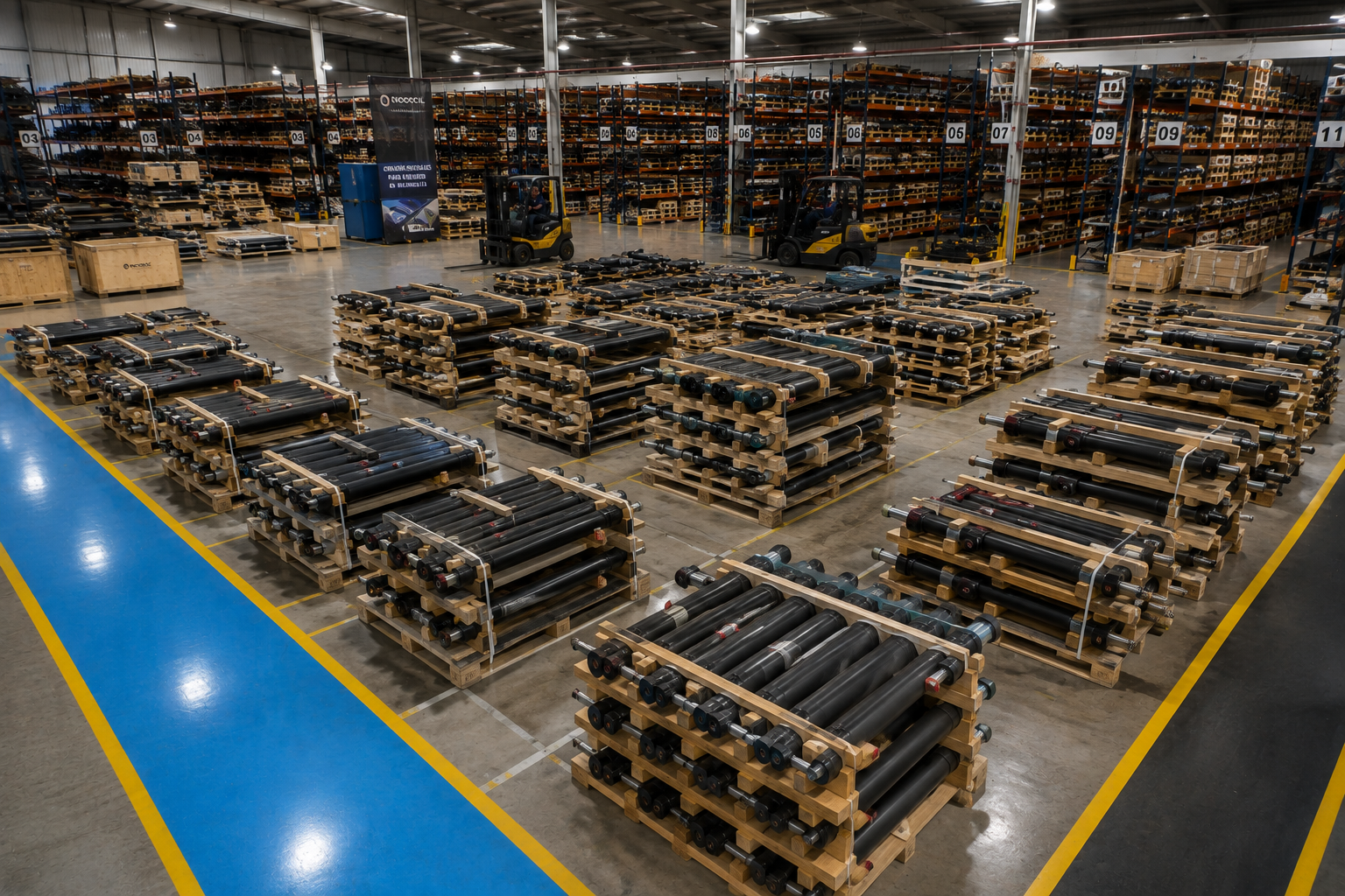
Equipment idle for months? What you need to know before reactivating your cylinders
Has your hydraulic equipment been idle in the yard for six months or more? Stored cylinders can suffer slow seal degradation and internal corrosion. Learn how to store and what to check before restarting.
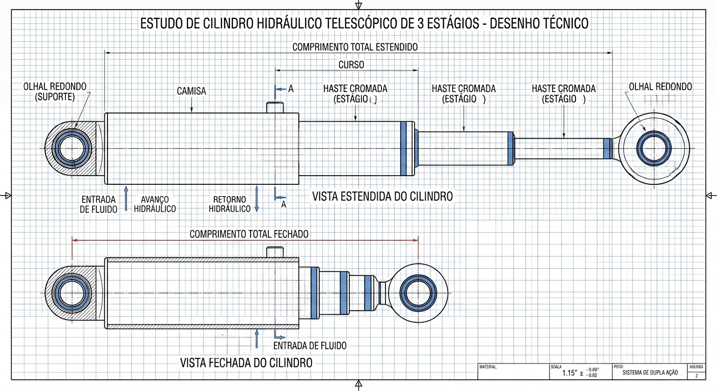
Telescopic Hydraulic Cylinder: How to Calculate Stroke, Stages, and Force at Each Stage
How to calculate total stroke, number of stages, and decreasing force at each stage of a telescopic hydraulic cylinder. Formulas, numerical example, and single vs. double-acting differences.
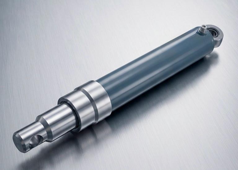
Single-Acting Hydraulic Cylinders: Types, Advantages, and How to Choose
A complete guide to single-acting hydraulic cylinders: learn the three types (Oil-over-Air, Buzo, and Ram), the advantages of each construction, and how to choose the right model for your application.